General:
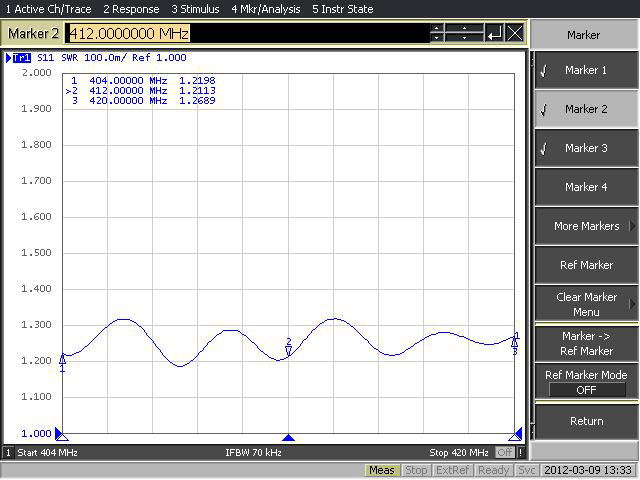
The SXO-4506 Stacked Dipole Antenna is a robust antenna with low VSWR and high gain covering 25 MHz. band with any selected centre frequency out of 330-512 MHz. band. It can be mounted on top of an antenna-tower for a Omni directional pattern or side mounted for an offset horizontal radiation pattern.
Design & Construction:
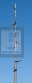
The SXO-4506 Stacked Dipole Antenna consists of FOUR folded dipoles stacked vertically. The antenna maintains constant gain and VSWR over its bandwidth of 20 MHz., making it highly suitable for single or multi-frequency systems. The feed ends and cable connections to the dipoles are sealed in epoxy at the end of the boom for protection against weather and imparting rigidity and strength to the dipole structure.
The dipoles are mounted on a tubular boom made of high strength aluminum alloy, which offers a low resistance discharge path. Molded phasing harness cable joints and N-Female antenna termination connector ensures complete waterproofing and many years of maintenance free operation.
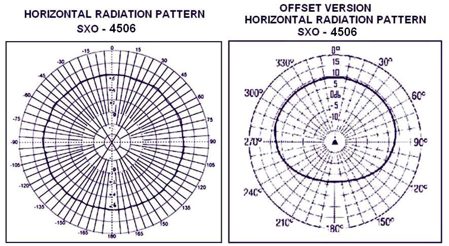
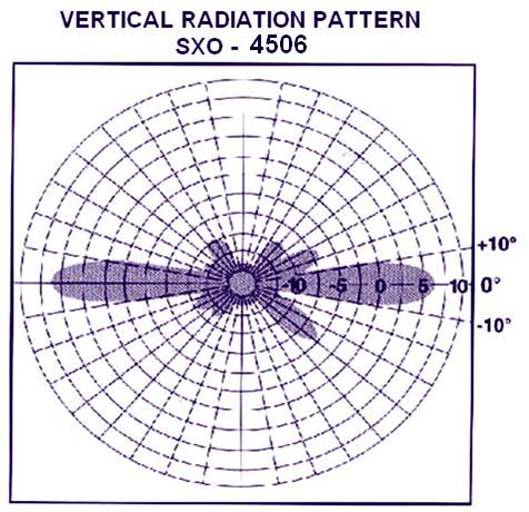
Radiation Pattern:
When the FOUR dipoles are arranged 90 degrees apart around the central mast, 6dBd. Omni directional radiation pattern results. Aligning the FOUR dipoles collinearly a 9dBd. offset radiation pattern is obtained. The radiation pattern can be changed in the field by use of common hand tools.
Phasing Harness:
Specially designed center fed phasing harness ensures equal and in phase signal distribution to all FOUR dipoles. All power splitter joints are molded to avoid use of connectors/adapters for waterproofing and to minimize loss.
Shipping:
For ease of handling, the 12 feet long central mast for mounting the dipoles is shipped in TWO sections of 6 feet each. It can be assembled with simple hand tools in the field with specially designed center coupling supplied with the antenna.
|